Add a Tier-0 Gateway

Hi, In my previous post, I

In the NSX-T. Now, I want to Add Tier-0 Gateways.

A tier-0 gateway has downlink connections to tier-1 gateways and external connections to physical networks.

You can configure the HA (high availability) mode of a tier-0 gateway to be active-active or active-standby. The following services are only supported in active-standby mode:

  • NAT
  • Load balancing
  • Stateful firewall
  • VPN

Tier-0 and tier-1 gateways support the following addressing configurations for all interfaces (external interfaces, service interfaces, and downlinks) in both single-tier and multi-tiered topologies.

Note:

You can configure the tier-0 gateway to support EVPN (Ethernet VPN).

1- Go to the Networking –> Connectivity –> Tier-0 Gateways –> Add Gateway –> Click Add Tier-0 Gateway.

2- Enter a name for the gateway.

3- Select an HA (high availability) mode.

The default mode is active-active. In the active-active mode, traffic is load balanced across all members. In active-standby mode, all traffic is processed by an elected active member. If the active member fails, a new member is elected to be active.

4- If the HA mode is active-standby, select a failover mode.

OptionDescription
PreemptiveIf the preferred node fails and recovers, it will preempt its peer and become the active node. The peer will change its state to standby.
Non-preemptiveIf the preferred node fails and recovers, it will check if its peer is the active node. If so, the preferred node will not preempt its peer and will be the standby node.

5- (Optional) Select an NSX Edge cluster.

6- (Optional) Click Additional Settings

  1. In the Internal Transit Subnet field, enter a subnet. This is the subnet used for communication between components within this gateway. The default is 169.254.0.0/24.
  2. In the T0-T1 Transit Subnets field, enter one or more subnets. These subnets are used for communication between this gateway and all tier-1 gateways that are linked to it. After you create this gateway and link a tier-1 gateway to it, you will see the actual IP address assigned to the link on the tier-0 gateway side and on the tier-1 gateway side. The address is displayed in Additional Settings > Router Links on the tier-0 gateway page and the tier-1 gateway page. The default is 100.64.0.0/16.
  3. In the Forwarding Up Timer field, enter a time. The forwarding up timer defines the time in seconds that the router must wait before sending the up notification after the first BGP session is established. This timer (previously known as forwarding delay) minimizes downtime in case of fail-overs for active-active or active-standby configurations of logical routers on NSX Edge that use dynamic routing (BGP). It should be set to the number of seconds an external router (TOR) takes to advertise all the routes to this router after the first BGP/BFD session. The timer value should be directly proportional to the number of northbound dynamic routes that the router must learn. This timer should be set to 0 on single-edge node setups.

7- Click Route Distinguisher for VRF Gateways to configure a route distinguisher admin address. This is only needed for EVPN in Inline mode.

8- (Optional) Click EVPN Settings to configure EVPN.

  1. Select an EVPN mode. The options are:
    • Inline – In this mode, EVPN handles both data plane and control plane traffic.
    • Route Server – Available only if this gateway’s HA mode is active-active. In this mode, EVPN handles control plane traffic only.
    • No EVPN
  2. If EVPN mode is Inline, select an EVPN/VXLAN VNI pool or create a new pool by clicking the menu icon (3 dots).
  3. If EVPN mode is Route Server, select an EVPN Tenant or create a new EVPN tenant by clicking the menu icon (3 dots).
  4. In the EVPN Tunnel Endpoint field, click Set to add EVPN local tunnel endpoints. For the tunnel endpoint, select an Edge node and specify an IP address. Optionally, you can specify the MTU.

9- To configure route redistribution, click Route Redistribution and Set.

Select one or more of the sources:

  • Tier-0 subnets: Static RoutesNAT IPIPsec Local IPDNS Forwarder IPEVPN TEP IPConnected Interfaces & Segments. Under Connected Interfaces & Segments, you can select one or more of the following: Service Interface SubnetExternal Interface SubnetLoopback Interface Subnet, or Connected Segment.
  • Advertised tier-1 subnets: DNS Forwarder IPStatic RoutesLB VIPNAT IPLB SNAT IPIPSec Local EndpointConnected Interfaces & Segments. Under Connected Interfaces & Segments, you can select Service Interface Subnet and/or Connected Segment.

Finish 🙂

Add Tier-1 Gateways

Hi, In my previous post, I

In the NSX-T. Now, I want to Add Tier-1 Gateways.

A tier-1 gateway is typically connected to a tier-0 gateway in the northbound direction and to segments in the southbound direction.

1- Go to the Networking–> Connectivity –> Tier-1 Gateways –> Add Tier-1 Gateways

2- Enter a name for the gateway: T1

Note:

(Optional) Select a tier-0 gateway to connect to this tier-1 gateway to create a multi-tier topology.

Note:

(Optional) Select an NSX Edge cluster if you want this tier-1 gateway to host stateful services such as NAT, load balancer, or firewall. If an NSX Edge cluster is selected, a service router will always be created, affecting the north/south traffic pattern.

I choose Edge-Cluster, Because I want to use load balancer and NAT in future post.

Note:

If you selected an NSX Edge cluster, select a failover mode or accept the default.

OptionDescription
PreemptiveIf the preferred NSX Edge node fails and recovers, it will preempt its peer and become the active node. The peer will change its state to standby.
Non-preemptiveIf the preferred NSX Edge node fails and recovers, it will check if its peer is the active node. If so, the preferred node will not preempt its peer and will be the standby node. This is the default option.

Note:

(Optional) Click the Enable Standby Relocation toggle to enable or disable standby relocation. Standby relocation means that if the Edge node where the active or standby logical router is running fails, a new standby logical router is created on another Edge node to maintain high availability. If the Edge node that fails is running the active logical router, the original standby logical router becomes the active logical router and a new standby logical router is created. If the Edge node that fails is running the standby logical router, the new standby logical router replaces it.

Note:

(Optional) Click Route Advertisement.

Select one or more of the following:

  • All Static Routes
  • All NAT IP’s
  • All DNS Forwarder Routes
  • All LB VIP Routes
  • All Connected Segments and Service Ports
  • All LB SNAT IP Routes
  • All IPsec Local Endpoints

Note:

(Optional) Click Route Advertisement.

In the Set Route Advertisement Rules field, click Set to add route advertisement rules.

Note:

(Optional) Click Service Interfaces and Set to configure connections to segments. Required in some topologies, such as VLAN-backed segments or one-arm load balancing.

a. Click Add Interface.

b. Enter a name and IP address in CIDR format.

c. Select a segment.

d. In the MTU field, enter a value between 64 and 9000.

f. Add one or more tags.

g. In the ND Profile field, select or create a profile.

h. Click Save.

Note:

(Optional) Click Static Routes and Set to configure static routes.

a. Click Add Static Route.

b. Enter a name and a network address in the CIDR or IPv6 CIDR format.

c. Click Set Next Hops to add next hop information.

d. Click Save.

Note:

(Optional) Click Multicast and then the toggle to enable multicast. You must select an Edge cluster for this gateway. Also, this gateway must be linked to a tier-0 gateway that has multicast enabled.

Finish 🙂

Add Edge Cluster

Hi, In my previous post, I

In the NSX-T. Now, I want to add an Edge Cluster.

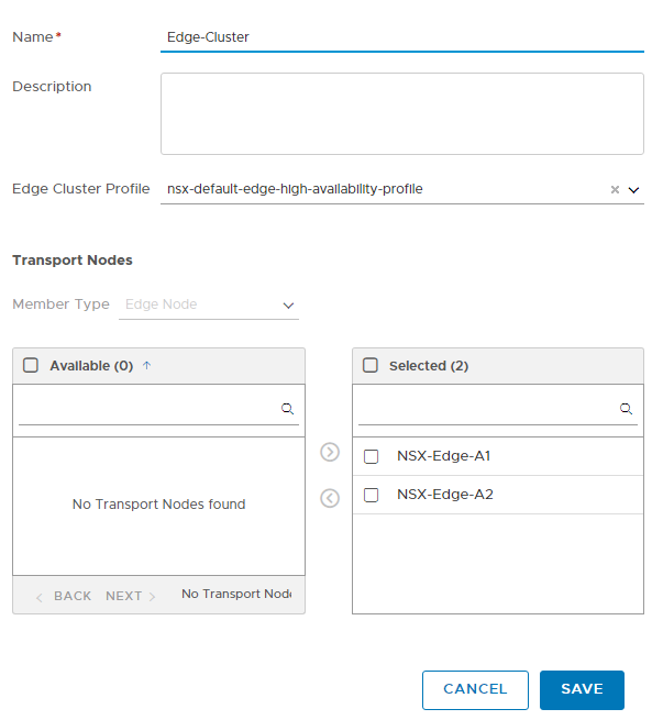
1- Go to the System –> Fabric–> Nodes –> Edge Clusters –> Add Edge Cluster

Save

Finish 🙂

Install NSX Edge2

Hi, In my previous post, I

In the NSX-T. Now, I want to install NSX Edge2.

1- Go to the System –> Fabric–> Nodes –> Edge Transport Nodes –> Add Edge Node

2- We must add two switches. One for Host Overlay and another for Host VLAN.

3- Add Host overlay switch

Enter Edge Name: NSX-Edge-A2

Enter the Edge switch name: nsxHostSwitchOverlay

Transport Zone: nsx-overlay-transportzone

Uplink Profile: khoshraftar-Edge-Transport-overlay-vetp-profile-single

IP Assignment: Use IP Pool

IP Pool: Edge-TEP-IP-POOL

Uplink2: Edge-Transport-overlay-vtep-Trunk

Note: We created this port group on the vCenter nested.

4- Add Host VLAN switch

Enter the Edge switch name: nsxHostSwitchVLAN

Transport Zone: nsx-vlan-transportzone

Uplink Profile: khoshraftar-Edge-VLAN-LoadBalance

Uplink2: Left-Uplink-Edge-Trunk

Uplink3: Right-Uplink-Edge-Trunk

Note: We created these port groups on the vCenter nested.

Click Save

Finish 🙂

Install NSX Edge1

Hi, In my previous post, I

In the NSX-T. Now, I want to install NSX Edge.

1- Go to the System –> Fabric–> Nodes –> Edge Transport Nodes –> Add Edge Node

2- We must add two switches. One for Host Overlay and another for Host VLAN.

3- Add Host overlay switch

Enter Edge Name: NSX-Edge-A1

Enter the Edge switch name: nsxHostSwitchOverlay

Transport Zone: nsx-overlay-transportzone

Uplink Profile: khoshraftar-Edge-Transport-overlay-vetp-profile-single

IP Assignment: Use IP Pool

IP Pool: Edge-TEP-IP-POOL

Uplink2: Edge-Transport-overlay-vtep-Trunk

Note: We created this port group on the vCenter nested.

4- Add Host VLAN switch

Enter the Edge switch name: nsxHostSwitchVLAN

Transport Zone: nsx-vlan-transportzone

Uplink Profile: khoshraftar-Edge-VLAN-LoadBalance

Uplink2: Left-Uplink-Edge-Trunk

Uplink3: Right-Uplink-Edge-Trunk

Note: We created these port groups on the vCenter nested.

Click Save

Finish 🙂

Add Segment

Hi, In my previous post, I

In the NSX-T. Now, I want To add a Segment.

In NSX-T Data Center, segments are virtual layer 2 domains. A segment was earlier called a logical
switch.
There are two types of segments in the NSX-T Data Center:

VLAN-backed segments
Overlay-backed segments

1- Go to the Networking–> Segment –> NSX –> Add Segment

2- Enter a name for your segment, and select a transport zone, I choose overlay.

To create a VLAN-backed segment, add the segment in a VLAN transport zone. Similarly, to create an overlay-backed segment, add the segment in an overlay transport zone.

Connected Gateway: I choose none.

Select this option when you do not want to connect the segment to any upstream gateway (tier-0 or

tier-1). Typically, you want to add a standalone segment in the following scenarios:

  • When you want to create a local testing environment for users that are running workloads on the same subnet.
  • When east-west connectivity with users on the other subnets is not necessary.
  • When north-south connectivity to users outside the data center is not necessary.
  • When you want to configure layer 2 bridging or guest VLAN tagging.

I explain other parameters in future posts.

This segment was created on the vCenter VDS switch as a Port Group with a VNI number.

Now, you can assign this port group to your VMs.

Finish 🙂

Prepare Host Transport Nodes

Hi, In my previous post, I

In the NSX-T. Now, I want To Prepare Host Transport Nodes.

1- Go to the system –> Nodes –> Managed by –> select your vCenter –> Select Your host –> Configure NSX

2- Check your Name and IP address is ok.

3- I want to use VDS, choose my VDS switch name Dswitch-A, select two transport zone profiles that were created in the previous post, and select an uplink profile for the Host that we created in the older post. For the IP TEP assignment, select IP POOL, and select Host-TEP-IP-Pool.

In our Uplink Profile, we selected two NICs, here we must select which uplink must be mapped to the uplink profile. Mu ESXi host has three uplinks, I choose uplinks 2 and 3.

4- Second Host, check your Name and IP address is ok.

5- NSX Configuration must be in Success mode.

Finish 🙂

Add Transport Zones

Hi, In my previous post, I

In the NSX-T. Now, I want to add Transport Zones.

1- Go to the system –> Transport Zones –> Transport Zones –> Add Zone

2- Create a Transport Zone for Overlay Traffic

3- Create a Transport Zone for VLAN Traffic

Finish 🙂

Add Uplink Profiles

Hi, In my previous post, I

In the NSX-T. Now, I want to add Uplink Profiles.

1- Go to the system –> Profiles –> Uplink Profiles –> Add Profile

2- I create a profile for Edge Transport Overlay with a single NIC

Note: I set VLAN 70 on this profile. Because I used to create a Trunk Port Group for Traffic Overlay. If you create a VLAN port group for overlay Traffic, you can set VLAN here to 0.

3- I create another profile for Edge VLAN with Two NICs.

Note: I set Transport VLAN 0 Because we create a VLAN profile, we don’t use it for overlay traffic, and we don’t need to set any VLAN.

4- I create a profile for Host VLAN and vtep with two NICs.

Note: I set VLAN 50 for overlay Traffic Because my port group is in Trunk mode.

Finish 🙂

Add IP Address Pools

Hi, In my previous post, I

To the NSX-T Cluster. Now, I want to add an IP address pool.

1- Go to the Networking–> IP address pool–> Add IP address Pool

2- Add Edge-TEP-IP-POOL first, Enter the name of the pool, Click on Set and choose IP Range

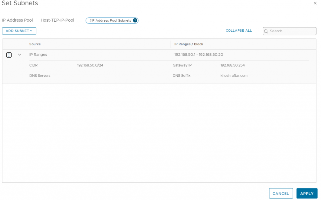
3- Set Your IP range, CIDR, DNS, and Gateway

4- Apply

5- Add Host-TEP-IP-Pool, Enter the name of the pool, Click on Set and choose IP Range

6- Set Your IP range, CIDR, DNS, and Gateway

7- Apply

8- Save

9- check the status, must be Success

Finish 🙂