Hi, Today I decided to change my VCSA 8.0 certificate. For this purpose, we must do 4 things:
- Create CSR from the vCenter server
- Get a Certificate from an authority CA (I use a Microsoft CA server)
- Install OpenSSL and Convert the CER format certificate to PEM format
- Assign it to vCenter
Let’s start.
1. Create CSR from the vCenter server:
1-1 Login to vCenter Server

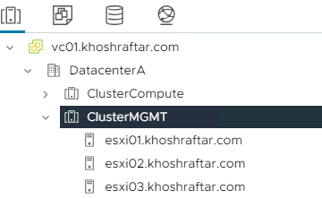
1-2 Go to the Inventory

1-3 Go to the Certificate –> Certificate Management –> Generate Certificate Signing Request(CSR)

1-4 Enter your information

1-5 Copy CSR Request

2. Get a Certificate from an authority CA (I use a Microsoft CA server)
2-1 Go to your Microsoft CA server (or other Authority Certificate) http;//your_CA-Server_IP/certsrv
Click on the “Request a certificate“

2-2 Click on the “advanced certificate request“

2-3 Past your CSR request here (We copy CSR Request in 1-5) and choose Web Server, then click submit.

2-4 Download Certificate (Base 64 encoded)

3. Install OpenSSL and Convert the CER format certificate to PEM format
3-1 Now, we need to convert this certificate to PEM, so we need a tool for covering the certificate.
I used OpenSSL tools.
How to install OpenSSL?

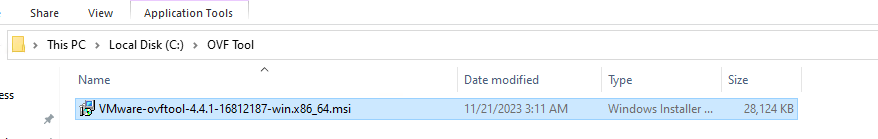
3-2 I downloaded the MSI version. And click on it.

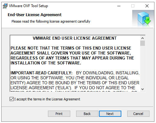
3-3 Accept the agrrement and Next.

3-4 Select a path for installation.

3-5 Next

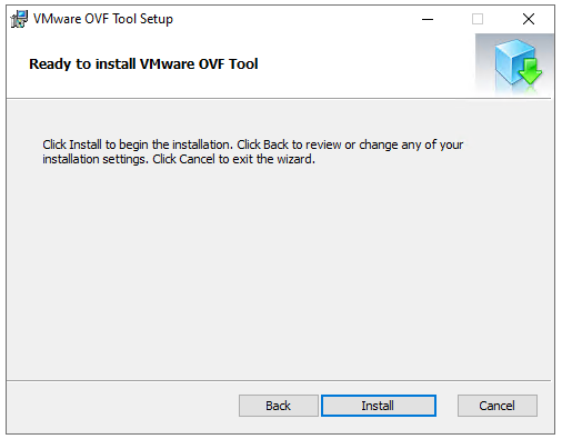
3-6 Click on the Install button.

3-7 Open the Command prompt as an administrator account, then go to the installation_path\OpenSSL-Win64\bin

3-8 Used this command to convert .cer to .pem. (for vCenter Server certificate)
openssl x509 -in certnew.cer -out certnew-vc01.pem
3-9 Used this command to convert .cer to .pem. (for root certificate)
openssl x509 -in root.cer -out root.pem
4. Assign it to vCenter
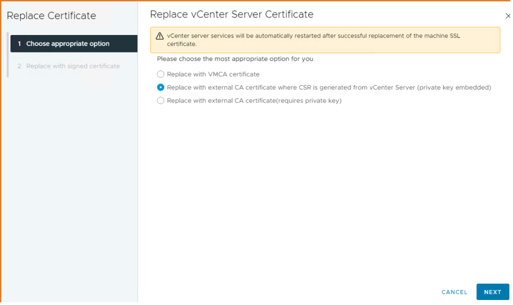
4-1 Now, click on the “Import and Replace Certificate” button.

4-2 Choose to Replace with external CA certificate where CSR is generated from vCenter Server.
4-3 Click on the Browse File button, then

4-4 Select vCenter PEM format certificate

4-5 Click on the Browse File button, then

4-6 Select root PEM format certificate

4-7 The vCenter ask you to wait some minutes and after that try to refresh your browser.

Finish 🙂


 7.
7. 


